Apr 2025 – May 2025
EELast edited
Resolution and Robustness of a Three-Microphone DOA System
Built a direction-of-arrival (DOA) system using three omnidirectional CMA-4544PF-W microphones arranged in an equilateral triangle. Each microphone is filtered, sampled by an MCP3201 12-bit ADC over SPI, and read by a Raspberry Pi using DMA before SFTP upload for offline analysis.
Direction estimates come from pairwise cross-correlation between channels: the lag that maximises each correlation gives the inter-microphone delay, and the three delays are combined into an angle of incidence. Systematic testing covered 0°, 90°, 110°, and 270°, with additional sweeps over microphone spacing, source distance, and background-noise conditions.
Average angular deviation was under 2° at most directions, with low standard deviation. The notable failure mode appeared at 270° and 300°, where both bias and variance jumped sharply, most likely from room reflections, finite angular resolution at small inter-mic spacing, and per-microphone gain or phase variation.
Affiliation
NTNU
Partners
Report
- Lab report
Keywords
- C
- Python
- Raspberry Pi
- MCP3201 ADC
- Digital Signal Processing (DSP)
- Cross-Correlation
- Time-Delay Estimation
▸ Deepdive
Introduction
This project is the second lab in NTNU’s TTT4280 Sensor og instrumentering sequence and reuses the multi-ADC acquisition pipeline from the first lab: a Raspberry Pi 3B+ driving Microchip MCP3201 12-bit ADCs over a shared, DMA-bit-banged SPI bus, with an LC supply filter on the 3.3 V rail. Here the analog front-end is three CMA-4544PF-W electret microphones arranged in an equilateral triangle, and the question is no longer “how close to the quantization bound does the chain run?” but “given three time-of-arrival measurements from a handclap, how well can you recover the direction the clap came from?” The answer turns out to be: very well at most angles (sub- mean error, low standard deviation), badly at a couple of structural-blind-spot angles ( and ), and counter-intuitively better in a moderately noisy room than in a silent one.
Problem Definition
Three omnidirectional microphones sit at known positions in the same plane as an unknown sound source at azimuth . A short broadband impulse, a handclap, produces a wavefront that reaches each microphone at slightly different times, and the system samples the three microphone signals synchronously at . Pairwise discrete cross-correlations recover the inter-microphone lags,
and the lag converts directly to a time delay . Under the plane-wave assumption (source far enough away that the wavefront is effectively flat across the array) and with the microphones placed in an ideal equilateral triangle, the three pairwise delays close into a closed-form azimuth estimator,
The system’s angular resolution is bounded above by how many distinct integer lags are physically possible between any two microphones. With inter-mic spacing and speed of sound ,
so a lag can take any integer in , giving distinct delays and therefore at most that many distinct estimable directions per pair. At that’s lags either side, or distinct delays; at it drops to either side, or delays, a quantization-floor on the angle estimate before any noise or geometry is introduced.
Approach
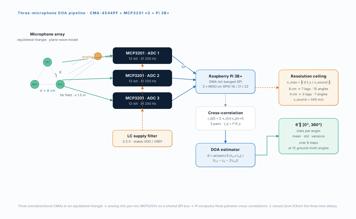
The pipeline reuses every piece of the digital chain from the predecessor lab and adds an acoustic front-end, three cross-correlations, and an angle estimator. Each subsection below covers one of those additions.
Microphone Front-End
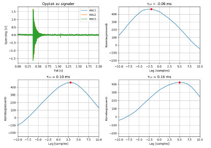
Three Murata CMA-4544PF-W electret condenser microphones, omnidirectional with a band and a specified SNR of , are arranged in an equilateral triangle on a breadboard with between centres (the reference configuration; a variant is tested separately). Each microphone shares the same rail and ground as the rest of the board and drives its own MCP3201’s IN+ input. Because every channel is referenced to the same VDD and the same VREF, an offset or gain mismatch between two mics shows up as a constant time-domain bias rather than as a varying delay, which is the property the cross-correlation depends on.
Synchronous Acquisition
The three MCP3201s share a single SPI clock and a single chip-select line, with each device’s MISO returning on its own GPIO (18, 21, 22). The pigpio-based bit-banged SPI master fires a single CS pulse, all three ADCs convert in lock-step, and the host reads the three MISO bits in the same SPI transaction. The lock-step is the load-bearing detail: any per-channel sampling jitter shows up directly as a spurious , and from there propagates through the to a biased , so anything that desynchronises the three ADCs is a noise source on the angle estimate.
Pairwise Cross-Correlation
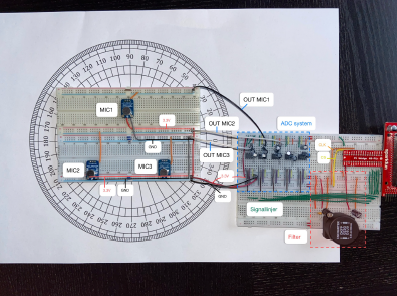
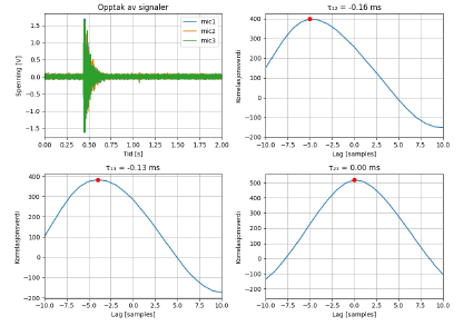
For each pair , the host computes over the recorded buffer and picks the lag of the maximum. Cross-correlation works best on signals with broadband content, handclaps in particular have a wide spectrum and a short temporal envelope, which produces a sharp, well-localised correlation peak and good immunity to in-band confusers. Autocorrelation of any individual channel is used as a sanity check (it must peak at by definition); a broken or desensitised mic stands out as a wide, low autocorrelation hump rather than the expected sharp spike.
Angle Estimation
The three delays plug into the closed-form above. Resolution is set entirely by , at , the system can distinguish delays per pair, which is what gates the angle resolution. The estimator assumes (i) the array is ideally equilateral, (ii) the wavefront is planar at the array, and (iii) the room is symmetric enough that no single mic sees a substantially earlier reflection than the others. Each of these assumptions becomes a controlled variable in the experimental section: shrinking tests the resolution ceiling, shrinking source distance tests the plane-wave assumption, and adding broadband background noise tests the correlation robustness.
Results
The reference configuration was tested at twelve ground-truth azimuths spanning , with independent handclaps per azimuth from in front of the array. The mean estimate sits within of the ground truth at most angles, with two structural blind spots: (standard deviation , variance ) and (standard deviation , variance ). The other ten angles all land at standard deviation , and most at .
| Ground-truth | Mean | Std | Variance |
|---|---|---|---|
A second batch of experiments varied one parameter at a time, all at a fixed ground-truth :
| Condition | Mean | Std | Variance |
|---|---|---|---|
| Reference (, , silent room) | |||
| (resolution test) | |||
| Source at (plane-wave test) | |||
| Background blue noise |
Three things in this second table are worth dwelling on. First, halving reduces the number of distinguishable lags per pair from to , so the quantization on doubles, and variance roughly doubles (), exactly the prediction from the formula. Second, putting the source from the array invalidates the plane-wave assumption: wavefronts arrive curved rather than flat, the become non-linear in the true geometry, and variance jumps by . Third, and this is the counter-intuitive result, adding broadband background noise reduces variance to its lowest value across all four conditions. The noise used was blue noise, which carries more energy at high frequencies than at low; combined with the impulsive clap, this broadens the signal’s spectrum and sharpens the cross-correlation peak, since correlation peaks are tighter when the input has flat broadband content rather than a few dominant low-frequency tones. The system isn’t merely robust to broadband background noise, it’s actively helped by it.
Future Work
The and blind spots are the largest open question in the reference configuration. Both directions fall in the back-half of the array, and the high variance at those angles co-occurs with several of the nine measurements landing at , a quantized-to-grid value rather than a noisy spread, which is the fingerprint of the resolution floor being hit rather than of stochastic noise. Two changes attack this: characterise each mic’s individual offset (one cheap calibration sweep with a known source) and subtract a per-channel bias on before the , and either tighten the equilateral geometry or move to a four-microphone tetrahedral arrangement that breaks the directional symmetry that makes ambiguous in the first place.
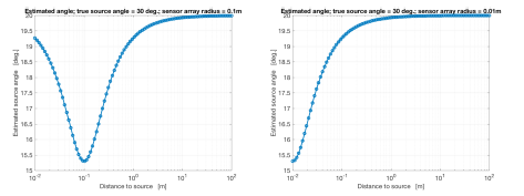
The plane-wave breakdown at short source distances is well-understood and quantified by the simulation in Figure 21, error grows sharply below from the array. For applications where the source is genuinely close (e.g. a wearable, or a hand-held listener that needs to localise a speaker away), the right fix is to replace the closed-form with a near-field model that treats each as a function of the position rather than just its azimuth, and to solve the resulting system numerically over a 2D grid. This is more compute per estimate but it’s compute the Pi has to spare in the current pipeline.
The most interesting redesign is to lean harder into the broadband-noise finding. The system already works better with blue noise present; injecting a known broadband probe signal (a chirp, a pseudo-random pulse train, or simply continuous low-level blue noise from a co-located speaker) and cross-correlating against the known reference rather than between two unknowns would convert the system from a passive impulse-localiser into an active sonar-style ranger, with all the precision benefits that come from controlling the source spectrum end-to-end. The cross-correlation machinery doesn’t change; only what’s correlated does.
Two lower-hanging fixes round out the next iteration: replace the breadboard build with a soldered PCB (the unexplained knee in the supply-filter response from the predecessor lab is almost certainly a layout artefact, and shows up here as additional in-band variance), and characterise each CMA-4544PF for sensitivity and self-noise before installation, since a single under-sensitive mic broadens its own correlation peak and biases every it contributes to. Both of these are mechanical improvements rather than algorithmic ones, but together they are the cheapest way to drive the reference-configuration standard deviation from toward the floor that the resolution ceiling at would in principle allow.